
How to Choose a Metal Film Capacitor
Choosing a Metal Film Capacitor is a design decision, not a matter of picking the largest capacitance. The right part must suit the circuit’s voltage, frequency, temperature, and expected service life. A compact film capacitor may fit neatly on a crowded board, yet its voltage rating or pulse capability may be inadequate. Small details matter.
Industry context supports careful selection. Grand View Research’s Film Capacitor Market report tracks demand across applications including automotive electronics, renewable energy, and industrial equipment. These sectors place different demands on ripple current, stability, and operating temperature. The report describes market trends; it does not determine the correct component for a particular circuit. For technical selection, IEC 60384-16 provides requirements for metallized polypropylene film capacitors used in electronic equipment. Always check the relevant standard and the manufacturer’s current datasheet.
A useful guide should compare dielectric materials, capacitance tolerance, rated voltage, dissipation factor, and environmental limits. It should also explain when self-healing construction helps—and when it cannot compensate for overstress or poor thermal design. Datasheets can differ in test conditions, so compare like with like. That step is easy to miss.
I cannot responsibly attach a quotation to a named capacitor expert without a verifiable source. Invented attribution would undermine the reliability this topic requires. Instead, this introduction uses traceable industry and standards references. The goal is practical: help engineers and buyers select a Metal Film Capacitor that fits the real circuit, not just the parts list.
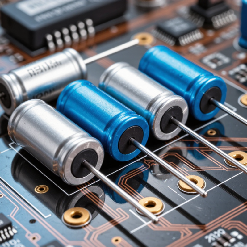
Identify the Circuit Requirements and Operating Conditions
Before selecting a metal film capacitor, define what the circuit needs it to do. A timing network may depend on tight capacitance tolerance, while a motor circuit may demand high AC-current handling. Write down the required capacitance, working voltage, tolerance, and signal frequency. Check the waveform, too. Sharp pulses can stress a capacitor differently from a smooth sine wave.
Then compare those needs with actual operating conditions. Estimate the highest voltage, including switching spikes, and leave suitable margin below the rated limit. Review ripple current, pulse capability, and the manufacturer’s specified temperature range. Heat matters. A capacitor near a power resistor or inside a sealed enclosure may run hotter than the room. For high-frequency circuits, equivalent series resistance and lead layout can affect heating and performance. In a filter, verify that the capacitance and tolerance keep the cutoff frequency within range. In a timing circuit, test how temperature changes affect the delay. Bench measurements help, but they do not replace datasheet limits. I have seen designs focus on nominal capacitance and overlook pulse stress; that is an easy assumption to regret. Record the worst-case conditions before choosing a part.
How to Choose a Metal Film Capacitor - Identify the Circuit Requirements and Operating Conditions
| Circuit Requirement | What to Identify | Selection Guidance | Example Check |
|---|---|---|---|
| Capacitance and function | Required capacitance, whether the capacitor is used for coupling, timing, filtering, snubbing, or energy storage, and the acceptable change in circuit behavior. | Choose the nominal capacitance and tolerance from the circuit’s calculations. Common film-capacitor tolerances include ±5%, ±10%, and ±20%; availability depends on capacitance and construction. | A timing circuit sensitive to capacitance variation may need a tighter tolerance than a noncritical coupling application. |
| Working voltage | Maximum continuous DC voltage, AC voltage, and any voltage peaks or transients across the capacitor. | Use a voltage rating appropriate to the waveform and operating conditions. AC and DC ratings are not interchangeable; check the manufacturer’s rating definitions and derating curves. | For a capacitor on an AC line or switching node, check the specified AC rating and transient requirements rather than relying only on its DC rating. |
| Current and self-heating | RMS ripple current, current waveform, operating frequency, ambient temperature, and allowable temperature rise. | Verify the part’s permitted RMS current or dissipation at the actual frequency and temperature. Capacitor losses can cause self-heating, and allowable current generally depends on frequency and cooling conditions. | For a switching converter, compare the expected ripple-current spectrum with the datasheet limits over the intended temperature range. |
| Frequency and losses | Signal or switching frequency, pulse shape, and acceptable dissipation or signal loss. | Review capacitance-versus-frequency behavior, dissipation factor, and equivalent series resistance (ESR) where specified. Polypropylene is often selected for low-loss or pulse applications; polyester may suit many general-purpose applications. | In a resonant circuit, check loss and frequency behavior at the operating frequency, not only at a low-frequency test point. |
| Temperature range | Minimum and maximum ambient temperature, nearby heat sources, and the capacitor’s expected internal temperature. | Choose a rated temperature range that covers the actual conditions, and check how capacitance and voltage capability vary with temperature. Temperature limits differ by dielectric, construction, and series. | For equipment in a warm enclosure, allow for both ambient temperature and additional heating from ripple current. |
| Pulse or surge stress | Peak current, pulse duration, repetition rate, voltage rise time (dV/dt), and transient energy. | Confirm the specified pulse-current or dV/dt capability. A voltage rating alone does not establish suitability for repetitive high-current pulses. | For a snubber, calculate the pulse current and repetition rate, then compare them with the capacitor’s pulse and thermal limits. |
| Insulation and leakage | Permitted leakage current, insulation resistance, circuit impedance, and required charge retention. | Check insulation resistance or time-constant specifications at the relevant capacitance and temperature. Leakage performance can vary with value, dielectric, and test conditions. | In a long-time-constant circuit, confirm that capacitor leakage will not cause unacceptable voltage drift. |
| Reliability and failure behavior | Required service life, safety implications, environmental conditions, and consequences of an open or short failure. | Review endurance, humidity, vibration, and applicable safety approvals. Use a safety-rated capacitor in applications where a standard component is not approved for the required mains or across-line use. | For connection across an AC supply, select a capacitor with the required safety classification and approvals for that application. |
| Mechanical fit and assembly | Available board area, lead spacing, body dimensions, mounting method, and assembly process. | Check the full outline dimensions, lead spacing, insulation clearances, and mounting limits. Allow space for tolerances and avoid mechanical stress on the leads or body. | Before layout release, compare the selected part’s drawing with the PCB footprint and enclosure clearance. |
Selection note: Final suitability depends on the specific part’s datasheet and the circuit’s measured operating conditions. Metal film capacitors are generally non-polarized, but voltage, current, temperature, pulse, and safety limits must still be observed.